


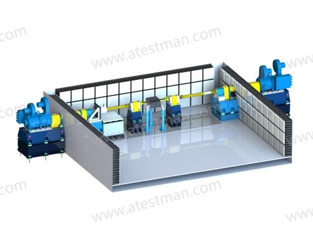
E-drive EMC Test bench
EMC dynamometer systems are widely used in electric drive systems,including: electric vehicle,electric drive systems, aerospace electric drive systems, and otherelectric drive applications that require radiated emissions and immunity testingof electric drive systems under load simulation. It meets relevant standards justas CIRSPR25,GB/T18655.GB/T36282,GB/T18387. It can restore real-world workscenarios of varies type EV.
Fit for varies testing scene as below:
-Direct driver testing (EV Motor/controller)
-EV driver system testing (Completed driver system)
-Two axis testing
-Movable module type system
Varies and customized solution available on requirement.
Features and Advantages

-Adopts special shielded technology for shaft through wall, with high speed, excellent shock resistance, high dynamic response, etc.;
-Can simulate various ground loop current status;
-Excellent EMC/EMI Performance
Emission:
10dB under the limits of CISPR25 of class5
Frequency range:10kHz~18GHz
Immunity:
Continuous field strength:200V/m
Frequency range:10kHz~18GHz
Product Spectrum
To meet different testing application scene, we offer varies models and system to full fill market expectation; Mainly as below:
Direct driver system
It provides EMC/EMI testing under real load scene for both commercial vehicles and passengers vehicles; This system aims to provide completed EV testing with minimize electromagnetic waves reflection area; Some of populate model list as shown on below table.
| T ype | N max (rpm) |
T rated (N *m) | Prated ( kw) | Nrated ( rpm) | N 2 ( rpm) |
Pamax(kw) @ N max |
Cooling |
|---|---|---|---|---|---|---|---|
| EMD-A120-075 | 7500 | 458 | 120 | 2500 | 5000 | 85 | Water |
| EMD-A173-15 | 15000 | 430 | 173 | 3840 | 13300 | 155 | Water |
| EMD-A250-16 | 16000 | 500 | 250 | 4773 | 14870 | 230 | Air |
| EMD-B300-15 | 15000 | 570 | 300 | 5026 | 12000 | 275 | Air |
| EMD-B300-12 | 10000 | 1000 | 300 | 2865 | 12000 | 300 | Air |
| EMD-C300-10/1 | 10000 | 2000 | 300 | 1433 | 10000 | 220 | Air |
| EMD-C300-10/2 | 10000 | 1300 | 300 | 2200 | 10000 | 300 | Air |
| EMD-C300-09 | 9000 | 1800 | 300 | 1591 | 9000 | 300 | Air |
| EMD-D370-07 | 7000 | 4000 | 370 | 883 | 3330 | 230 | Air |
| EMD-E500-06 | 6000 | 4500 | 500 | 1060 | 5000 | 400 | Air |
EV driver system testing (Completed driver system)
This is for general muti-purpose EMC/EMI test dynamometer system which meets completed EV testing and also fit for drive system testing; It’s very cost efficiency for those Customers which expecting muti-purpose test bench;
The configuration of this type test bench combines with motor and gear box which can make different torques and speeds combination testing scenes, just as high-speed and low-torque, low-speed and high-torque; However, due to gear box added in this system which increase electromagnetic waves reflection area; oil/gas potential emission inside the anechoic chamber, and it’s also may affect the antenna direction arrangement; Some of models which selected by market as below: (More Customized models available).
| T ype | N max (rpm) |
T rated (N *m) | Prated ( kw) | Nrated ( rpm) | N 2 ( rpm) |
Pamax(kw) @ N max |
Cooling |
|---|---|---|---|---|---|---|---|
| EMD-E370-20/60 |
6000 2 0000 |
4000 5 00 |
370 | 883 | 3330 | 230 | Air |
| EMD-E480-20/06 |
6 000 2 0000 |
4500 5 00 |
480 | 1310 | 4500 | 350 | Air |
Two axis testing system
This model adopts two motor drive dynamometer which can most close to real road scene to all vehicles. The two driving motors located at both side, it’s not need to lock the differential device on transaxle to provide two different torque to the both wheels. It can meet’s varies type vehicles, driver system, motors and construction equipment testing demands; Some of models which selected by market as below: (More Customized models available).
| T ype | N max (rpm) |
T rated (N *m) | Prated ( kw) | Nrated ( rpm) | N 2 ( rpm) |
Pamax(kw) @ N max |
Cooling |
|---|---|---|---|---|---|---|---|
| EMD-B300-12-2 | 12000 | 1000 | 300 | 2865 | 12000 | 300 | Air |
| EMD-E370-05-02 | 5000 | 3500 | 370 | 716 | 3000 | 230 | Air |
Movable module type system
This model applies for modularized design to all the units with compacted and easy mobilization advantage, it can be moved into anechoic chamber and connection for completed bench setup for testing in a short time; The system drive inverter, battery simulator, cooling system will locate at outside the anechoic chamber. The connection through EMC filter connection box of the anechoic chamber with plug-in connectors; This model will not take up the anechoic chamber permanently which will increase the anechoic chamber utilization efficiency; Due to dual-test driving system included, the initial investment will higher that models; Some of models which selected by market as below: (More Customized models available).
| T ype | N max (rpm) |
T rated (N *m) | Prated ( kw) | Nrated ( rpm) | N 2 ( rpm) |
Pamax(kw) @ N max |
Cooling |
|---|---|---|---|---|---|---|---|
| EMD-A115-02-2M | 2 000 | 1098 | 115 | 1000 | 2000 | 115 | W ater |
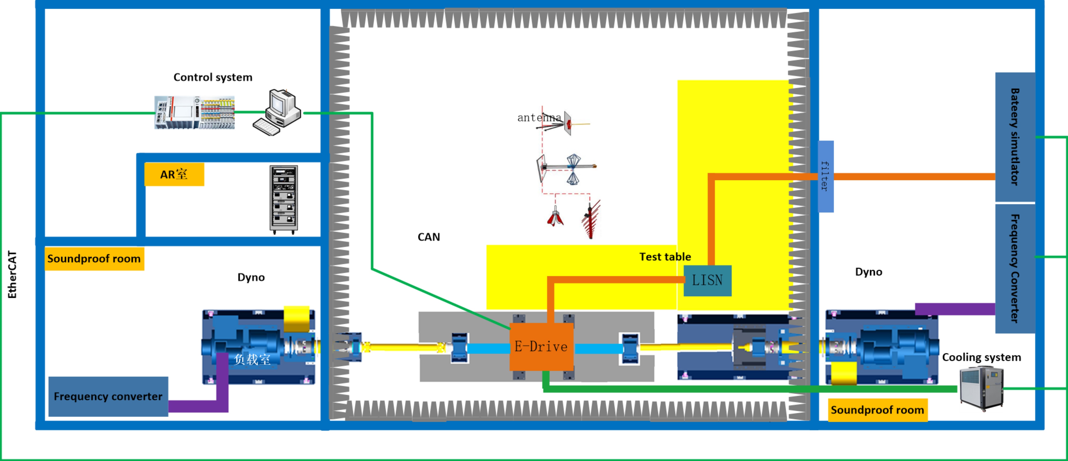
Functional Architecture Diagram
As a turn key solutions provider, we provide not only equipment, we also provide equipment installation infrastructure design and construction. Just as anechoic chamber designation, construction, installation and commissioning. Below is a typical system architecture diagram.
The measuring and control software integrates dynamometer control, battery simulator control, cooling system control and safety monitoring. The GUI can display torque, speed, current, voltage, temperature and other status value. It can realize the emergency braking, working condition control and other functions of the dynamometer.
·User management
·Dyno steady control (torque and speed)
·Dyno custom excel-based control
·Sensor calibration
·Auxiliary equipment: battery simulator, cooling system remote control etc.
·Alarm value setting
·Data store
·Data export
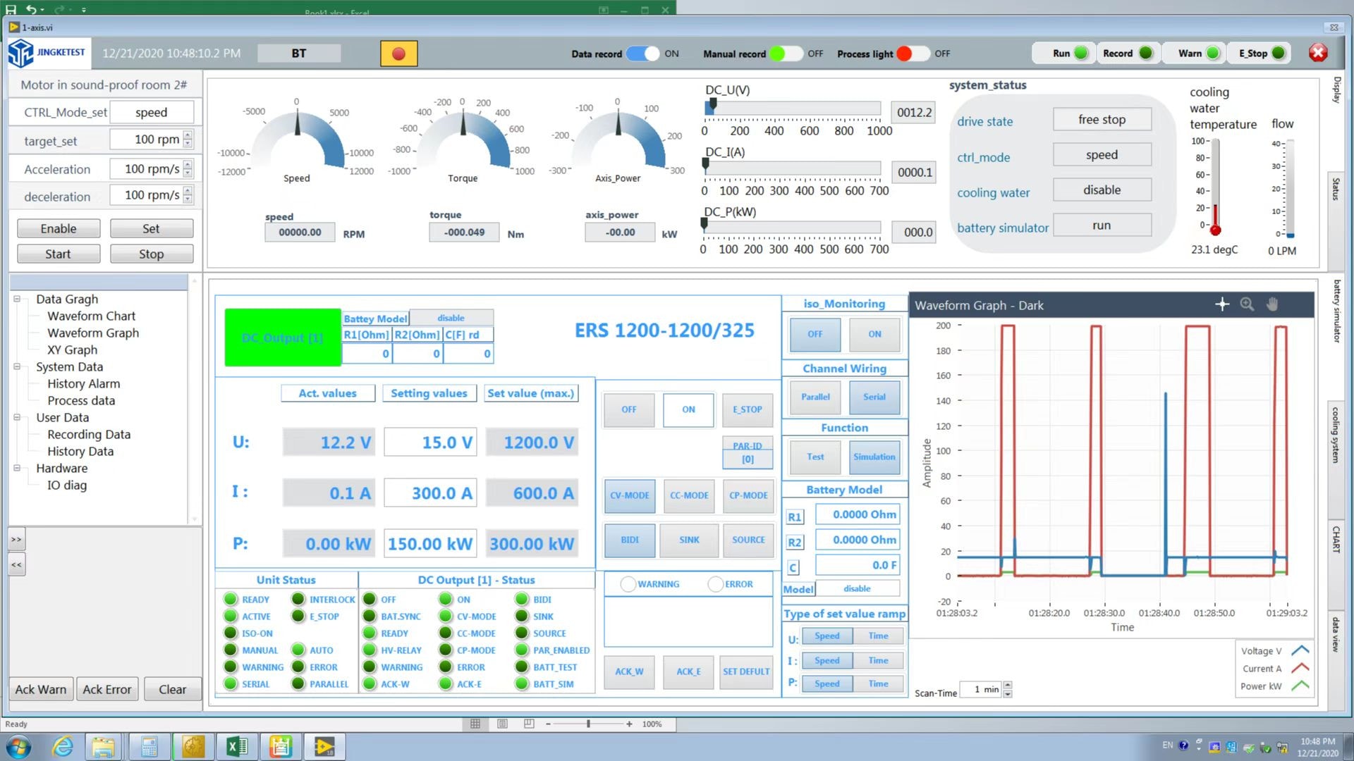
The measuring and control software integrates dynamometer control, battery simulator control, cooling system control and safety monitoring. The GUI can display torque, speed, current, voltage, temperature and other status value. It can realize the emergency braking, working condition control and other functions of the dynamometer.
1) A closing detection sensor is installed on the protective cover of the high-speed rotating part to detect whether the protective cover is closed in place;
2) The electrical system has the protection functions of leakage, short circuit and power failure;
3) A fault warning light shall be installed near the test bench and operation bench, and a red emergency stop button that cannot be reset shall be installed.
4) If the monitoring data of torque, rotating speed, pressure, temperature, vibration and other sensors are abnormal, the system will automatically alarm and then make an emergency stop;
5) In case of emergency, you can manually press the emergency stop button on the control cabinet panel to quickly stop the motor. The control cabinet is equipped with working and alarm display devices. When the system alarms, it will send out buzzer and red flashing light; When the system operates normally, it will emit green light;
6) In order to prevent the loss of test data caused by sudden power failure of the power grid, UPS power supply is used as the backup power supply in the control system, which can temporarily supply power to the industrial computer after power failure, and the test personnel can save the test data in time.
Connect with the right expert now.
Atestman offers solutions across your project development, delivery and supply globally,
so we need your help to match you with the right experts in the right place.
")
")
")