


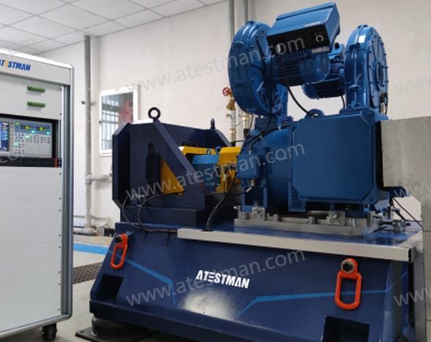
High-speed Motor Test Bench
It designed for varies high speed motor under vires application scene just as EV driving motor, high-speed magnetic levitation motor ext. With real-time dynamic control system, this system can detect the speed and torque control through the real-time controller and simulate the actual load. The main control system with interface for the environmental chamber, power analyzer, cooling system, EUT, etc., and realize control.Through gearbox, it can reach ultra-high speed up to 165000rpm even more on request.
Features and Advantages

-Ultra-high speed up to: 165,000rpm available;
-Long service lift;
-10ms dynamic system response time (Non load);
-Precise high speed bearing bracket with easy coupling designation structure;
-Completed monitoring software with.
Product Spectrum
Small high-speed motor test system
The small high-speed motor test bench (test system) is used to test low-power high-speed motors. It is mainly used for low-power aviation generators, robot motors, small high-speed compressor motors, machine tool spindle motors, etc. Motor test. The installation platform can be designed according to the motor to be tested, and the end flange installation structure or the base installation structure can be selected.
Select the dynamometer according to the characteristic curves of the motors intend to test. The dynamometer is generally controlled by a four-quadrant inverter and can work in electric model or power generation model. The system can be equipped with high and low temperature environment chamber, battery simulator or DC bidirectional power supply, low power Adjustable DC power supply, power analyzer, cooling system and other accessories. According to users' requirements for noise, water-cooled dynamometer or air-cooled dynamometer can be selected,
The recommended dynamometer parameters are as follows:
1.1 Small high speed motor dynamometer(Air-cooled type)
| Type | T r (N.m) | P r (kW) | n r (rpm) | n 2 (rpm) | n max (rpm) | P max (kW)@n max | Accuracy class |
|---|---|---|---|---|---|---|---|
| LD-AF1 | 3.6 | 4.5 | 12000 | 15000 | 24000 | 2 | 0.1%FS |
| LD-AF2 | 5.1 | 7.0 | 13000 | 19000 | 24000 | 4 | 0.1%FS |
| LD-AF3 | 14 | 7.5 | 3600 | 20000 | 20000 | 6 | 0.1%FS |
| LD-BF 1 | 37 | 14 | 3600 | 18000 | 18000 | 1 4 .0 | 0.05%FS |
| LD-BF 2 | 49 | 30.5 | 6000 | 9500 | 15000 | 24.0 | 0.05%FS |
1.2 Small high speed motor dynamometer(Water-cooled type)
| Type | T r (N.m) | P r (kW) | n r (rpm) | n 2 (rpm) | n max (rpm) | P max (kW)@n max | Accuracy class |
|---|---|---|---|---|---|---|---|
| LD-AW1 | 0.76 | 6 | 75000 | 75000 | 75000 | 6 | 0.1%FS |
| LD-AW2 | 1. 95 | 6 | 29400 | 40000 | 40000 | 6 | 0.1%FS |
| LD-AW 3 | 1.97 | 10.5 | 51000 | 60000 | 60000 | 10.5 | 0.1%FS |
| LD-AW 5 | 3.5 | 11 | 30000 | 42000 | 50000 | 9 | 0.1%FS |
| LD-AW 8 | 6.36 | 20 | 30000 | 30000 | 30000 | 20 | 0.1%FS |
| LD-AW 9 | 10.2 | 32 | 30000 | 50000 | 50000 | 10.2 | 0.1%FS |
| LD- B W1 | 20 | 12.1 | 5777 | 13000 | 24000 | 5 | 0. 05 %FS |
| LD- B W2 | 3 0.7 | 20 | 6215 | 24000 | 24 000 | 9.0 | 0.05%FS |
| LD- B W 3 | 35 | 22 | 6000 | 20000 | 20000 | 22 | 0. 05 %FS |
| LD- C W 1 | 5 0.8 | 2 5 | 4700 | 1 8 000 | 18000 | 25 | 0.05%FS |
| LD- C W 4 | 95.5 | 30 | 3000 | 10000 | 10000 | 30 | 0.05%FS |
| LD- D W1 | 115 | 32 | 2650 | 5800 | 15000 | 10 | 0.05%FS |
High speed and power motor testbench series
The high-speed and high-power motor test bench (test system) can be used in various high-speed motor applications such as new energy vehicle drive motors, high-speed air compressor motors, and high-speed magnetic levitation motors. The installation platform can be designed according to the motor to be tested, and the end flange installation structure or the base installation structure can be selected.
Select the dynamometer according to the characteristic curve of the motor intend to test. The dynamometer is generally controlled by a four-quadrant inverter which can work in electric model or power generation model. The system can be equipped with high and low temperature environment chambers, battery simulators or DC bidirectional power supplies, and power analysis Instrument, cooling system and other accessories.
The recommended dynamometer parameters are as follows:
| Type | n max (rpm) | T r (N.m) | P r (kW) | n r (rpm) | n 2 (rpm) | P max (kW)@ n max | Cooling |
|---|---|---|---|---|---|---|---|
| MD-A173-15-EP | 15000 | 430 | 173 | 3840 | 13300 | 155 | Fan |
| MD-A230-16-EP | 16000 | 500 | 230 | 4390 | 11000 | 155 | Liquid |
| MD-B250-16-EP | 16000 | 500 | 250 | 4773 | 14870 | 230 | Fan |
| MD-B250-17-EP | 17000 | 500 | 260 | 4966 | 15000 | 235 | Fan |
| MD-B300-20-EP | 20000 | 5 00 | 400 | 7 640 | 20000 | 400 | Liquid |
| MD-B350-25-EP | 2 5 000 | 500 | 350 | 6685 | 2 0 000 | 250 | Liquid |
| MD-C300-12-EP | 12000 | 1200 |
300 (500) |
2387.5(3980) | 12000 |
300 (500) |
Fan |
| MD-C300-10-EP | 10000 | 2000 | 300 | 1432.5 | 7500 | 220 | Fan |
| MD-C500-09-EP | 9000 | 3000 | 500 | 1619 | 5000 | 300 | Fan |
| MD-C440-07-EP | 7500 | 3500 | 440 | 1200 | 7500 | 440 | Fan |
| MD-C370-06-EP | 6000 | 4500 |
370 (500) |
785 (1061) |
6000 |
370 (500) |
Fan |
Notes: E—environmental chamber
P—Battery simulator/DC power supply
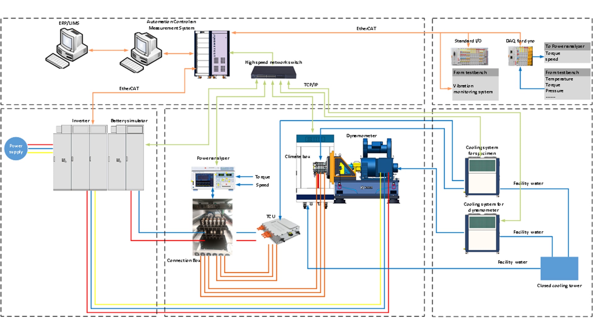
Functional Architecture Diagram
The measuring and control software integrates dynamometer control, battery simulator control, cooling system control, and safety monitoring. The GUI can display torque, speed, current, voltage, temperature and other status value. It can realize the emergency braking, working condition control and other functions of the dynamometer.
·User management
·Dyno steady control (torque and speed)
·Dyno custom excel-based control
·Sensor calibration
·Auxiliary equipment: battey simulator, cooling system remote control etc.
·Alarm parameters setting
·Data store
·Data export
1 Technical Requirement
·Ambient temperature:5℃~40℃
·Relative humidity: 20%....90%,not condensing
·The cooling water < 30 ℃ is provided by the customer, and the water connection point is installed at the designated location. The detailed technical requirements will be determined during the review of the technical proposal.
·The laboratory shall have good ventilation and exhaust function, and the ventilation and exhaust system shall be provided by Party A.
·Compressed air pressure: (0.5~0.6) Mpa, Party A shall provide compressed air after drying.
2 Main test parameters
a)Load characteristic test: measure the characteristics of the test motor under different loads. The measured data include:
1)Torque
2)Speed
3)Current
4)Voltage
5)Power
6)Map efficiency diagram
7)Power factor
8)Temperature
b)Motor response characteristic test(optional)
c)Harmonic analysis(optional)
d)No load test, disconnect the dynamometer coupling, and the measurement data include:
1)Current
2)Voltage
3)Speed
e)Locked rotor test, dynamometer shaft locked rotor, measurement data include:
1)Locked current
2)Locked torque
3)Locked voltage
f)Back EMF constant and waveform
g)Electromechanical time constant
3 Main Technical Parameters
1)Torque measurement control accuracy:±0.05%FS/±0.1%FS
2)Speed sensor pulse resolution: max 2048ppr
3)Torque control accuracy:±0.5%FS~±1%FS
4)Steady state speed control accuracy:±1rpm(≤10000rpm),±0.1%FS(>10000rpm)
5)DAQ sampling rate:1kHz
6)User data acquisition system channel: optional
7)Temperature sensor measuring range:-50℃~200℃
4 Testbed Mechanics
The speed rises from 0 r/min to the maximum speed, and the vibration speed(RMS) of the dynamometer and bearing support is evaluated according to GB/T 6075.3-2011/ISO 10816, and the RSM (mm/s) of vibration speed must be in the A or B area.
5 General Discription Of Mechanics
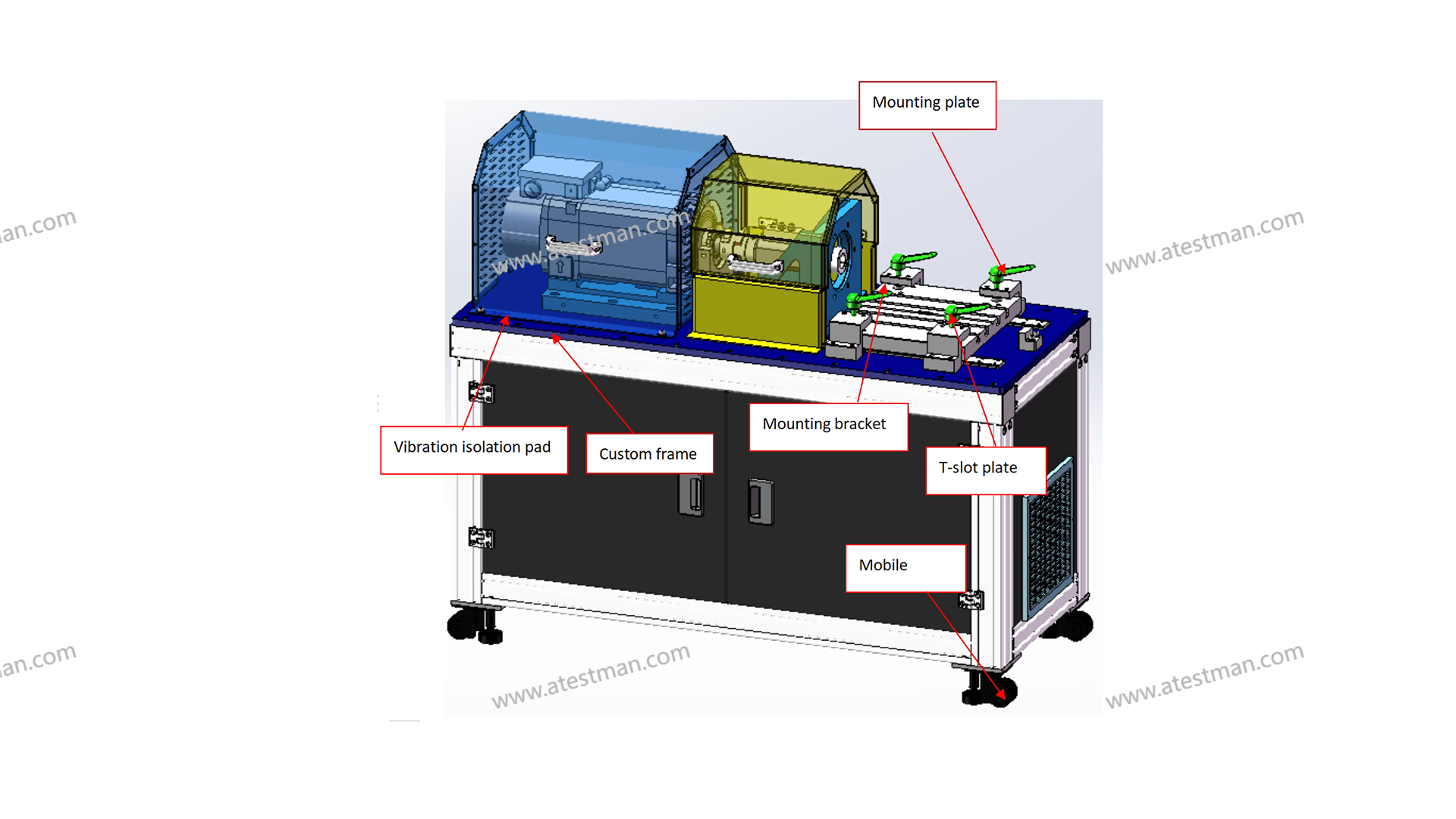
For illustration only
Mounting plate, T-slot plate, dynamometer and mounting plate, mounting bracket are mounted on the custom frame, and between the mounting plate and the custom frame, there are vibration isolation pad. The custom frame is spliced with aluminum alloy profiles or welded with steel. A universal wheel (if necessary) is installed at the bottom of the custom frame to facilitate the movement of the bench.
6 High speed Couling
The high-speed coupling is installed between the dynamometer output and the intermediate bearing support to avoid the damage caused by poor co-axiality.
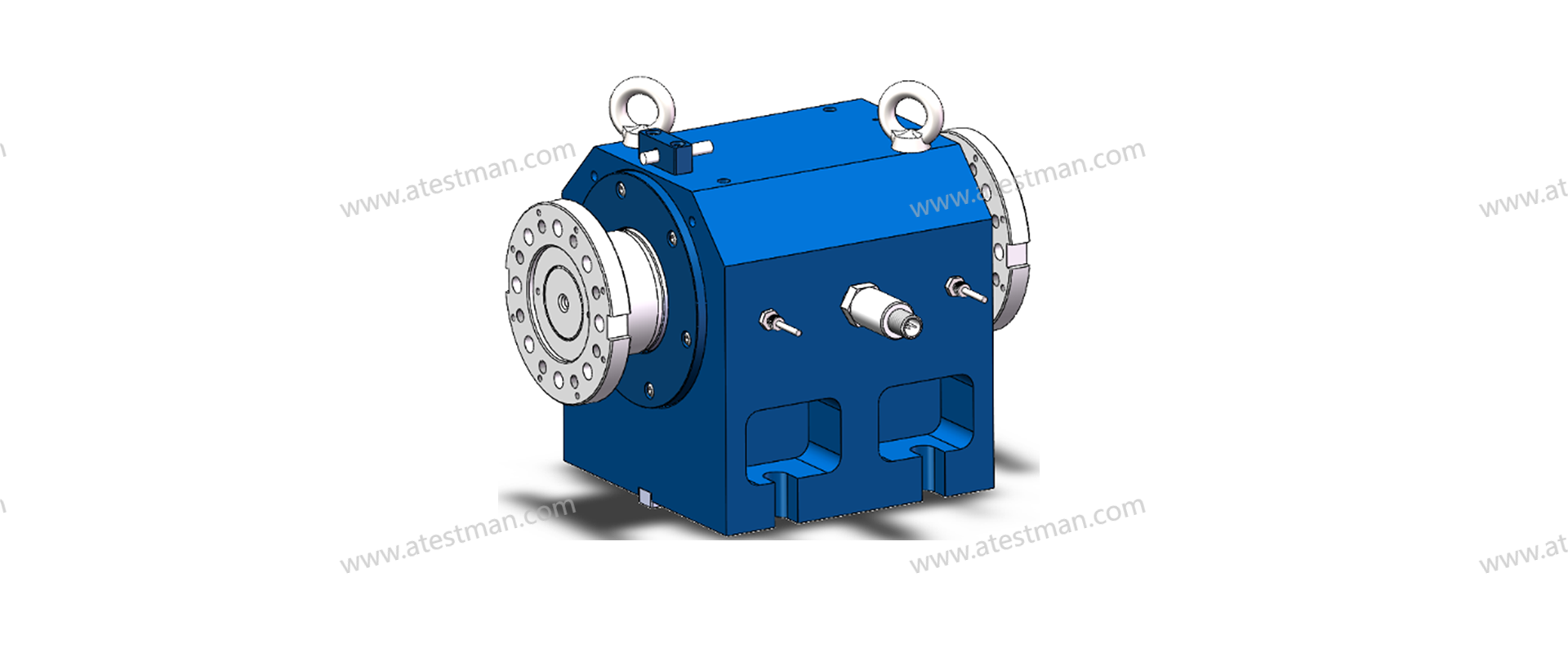
7 Intermediate Bearing Support
The intermediate bearing support auxiliary support the shaft system, and can avoid the influence of misalignment of the specimen installation to the shaft through Anechoic chamber. It has four high speed angular contact ball bearing, and the is fixed on the L-shaped mounting bracket (the mounting bracket of the e-motor). The concentricity between the shaft of the intermediate bearing support and the positioning circle of the specimen on the L-shaped mounting frame less than 0.02mm, and the perpendicularity to the positioning surface less than 0.02mm.
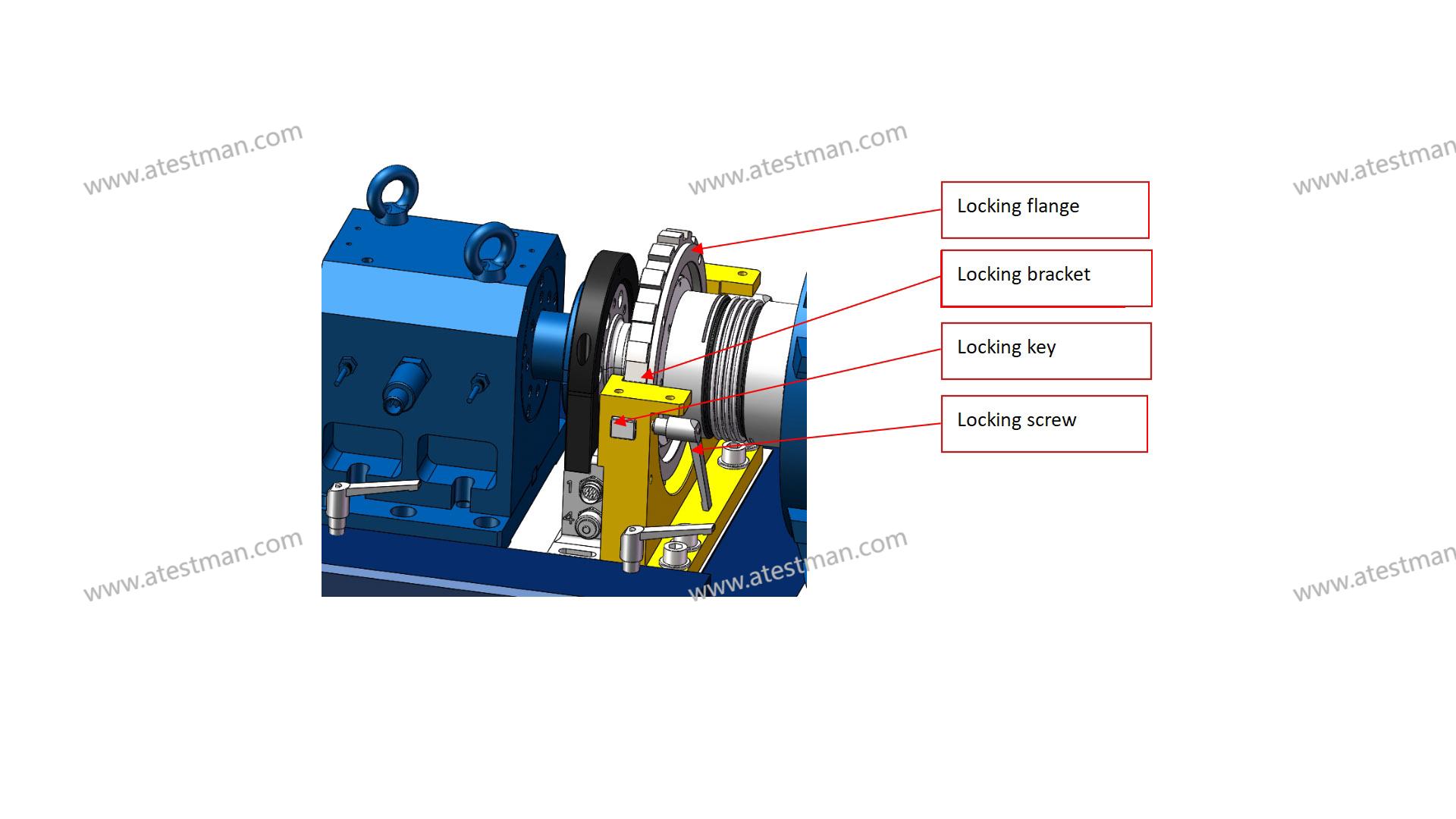
8 Shaft Locking Device
The locking device is used for locking shaft, which adopts the mechanical locking mode. The locking flange is designed with 10 locking positions (number can be customized).
The locking key is designed on both sides of the locking bracket. When the locking the shaft, push the locking key into the flange keyway and lock the locking key through the locking screw.
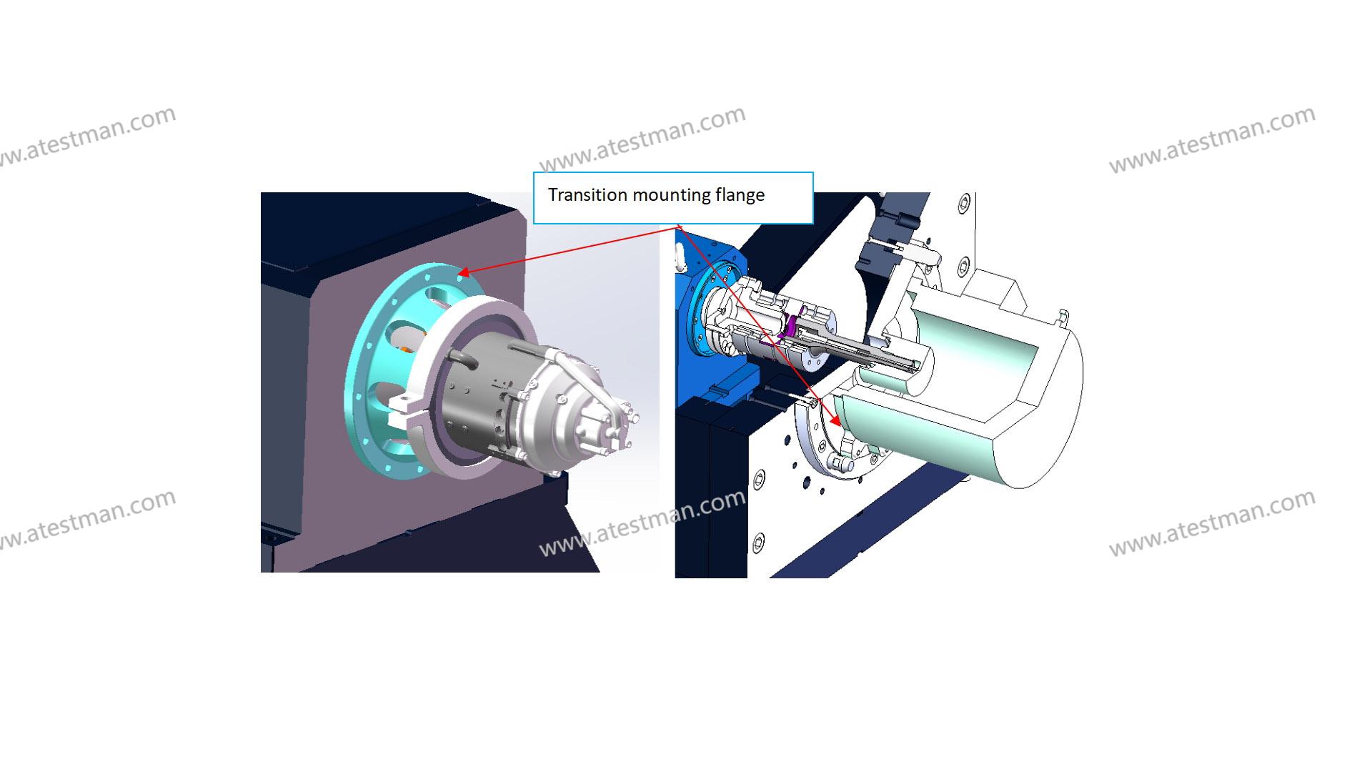
9 Mounting Bracket E-motor
The e-motor mounting bracket is used to mount the centrical mounting e-motor. The specimen is mounted on the end face of the mounting bracket through the transition mounting flange, positioned through the positioning spigot, and locked with bolts.
10 Safety Device
All rotating shafts have safety covers to protect the personnel from unintentional contact with the rotating shafts. The safety covers have closing detection switches. Only after the safety cover is closed, the dynamometer system would be started.
11 Load Unit
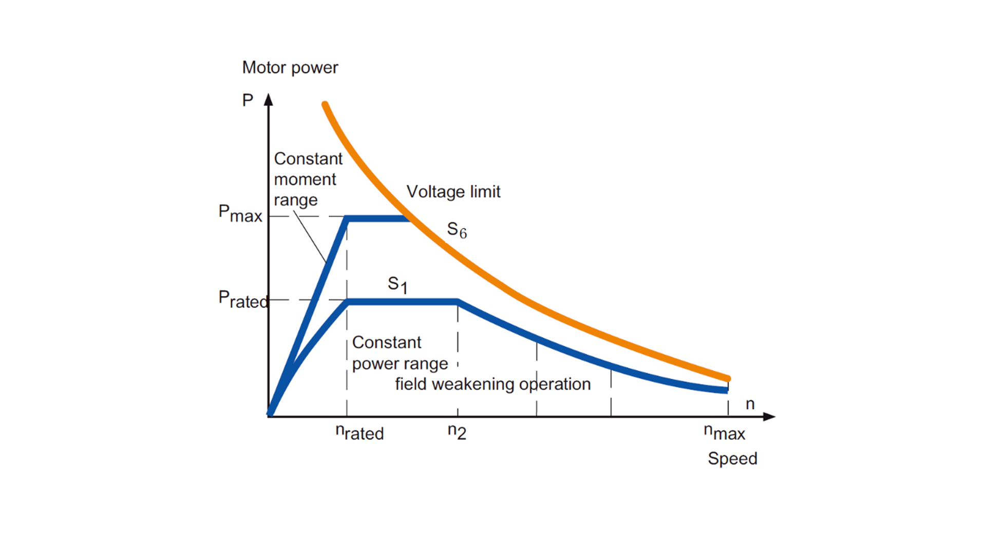
11.1 Dynamometer
Generally, The S1 working curve of dynamometer is selected according to the peak curve of the tested motor. The overload capacity of dynamometers is generally measured by S6 (40%) as the overload curve of dynamometers.
11.2Motor Inverter
System drives are compatible with all kinds of processes. They control virtually any type of AC motor, provide extensive input/output connectivity and support all major fieldbus protocols. The drives cover a wide voltage and power range. Control performance is scalable from basic to demanding applications delivered by direct torque control (DTC).
Connect with the right expert now.
Atestman offers solutions across your project development, delivery and supply globally,
so we need your help to match you with the right experts in the right place.

")