


Vehicle EMC/EMI Hub-mounted Chassis Dynamometer
This dynamometer system with four separated units for vehicle testing. Four independent dynamometer unit can carry out different torque and speed control to simulate vehicle real road loading; It fit both anechoic chamber and reverberation chamber testing with varies associative system just: exhausted emission system, vehicle withdraw system and other system on required;
Features and Advantages

-Each dynamometer unit is an independent unit.
-Each dynamometer unit can carry out independent torque or speed control to simulate road load.
-It can be used for vehicle test in anechoic chamber or reverberation chamber.
-Customized design can be carried out according to user needs.
-The wheelbase of multi axle dynamometer is adjustable to adapt to vehicle testing with different wheelbase.
-It can be equipped with automatic driving robot, exhaust emission system, vehicle windward system, etc.
-The unique shielding technology can meet the requirements of CISPR12, GB/T 18387-2008.
-The dynamometer can be of mobile structure or embedded installation.
-The vehicle fixing device is integrated with the dynamometer body, which is firm and reliable.
Product Spectrum
Free-Standing EMC/EMI Chassis Dynamometer
The free-standing chassis dynamometer generally for EMC/MEI testing. Key components included: an anechoic chamber or reverberation chamber, detecting/measuring instruments, cooling system and a hub dynamometer system that simulates the road load of the vehicle, environmental simulator(Option). The driver system, cooling system can be located outside the anechoic chamber.
| Diameter rollers | 2x(Ø240mm ) |
| Number Dyno | 2 / Axle |
| Rated Power | 22.5kW ( 45kW/ Axle) |
| Max speeds for cars | 1 0 0km/h |
| Permissible axle load | 2 t/ Axle |
| Axle distance | 1 8 00mm ~3200mm( or customized ) |
| Inner | Outer Roller edges | 100 0mm~2200mm |
| Own weight per module | 1300kg |
| Width | Depth per module | 2500mm|1250mm |
| Working Temperature range | 0 to + 35 ° C |
| Current Consumption | Max. approx. 145A |
| Voltage | 400V|3~+PE|50~60Hz,(or customized) |
Compares to embedded EMC chassis system, this free-standing type is not any fixed infrastructure required. It’s significantly increasing the utilization of the costly anechoic chamber.
Some popular models as below table listed:
| Type | Prated (kW) | Frated (N) (b) / 轴 | Vmax (km/h) | Vrtated (rpm) | F2 (N)@ Vmax / 轴 |
| ECD-A22-X(a) | 22 | 2600 | 120 | 60 | 1300 |
| ECD-B34-X | 34 | 3000 | 120 | 60 | 2035 |
Note:
(a) X—represents the number of axles of the dynamometer (for example: a four-wheel drive vehicle, generally use a 2-axis drive dynamometer).
(b) Frated—represents the traction of a single drive shaft of the dynamometer. The overall traction force of the dynamometer system is the number of active axles of the dynamometer multiplied by the traction force of a single axle.
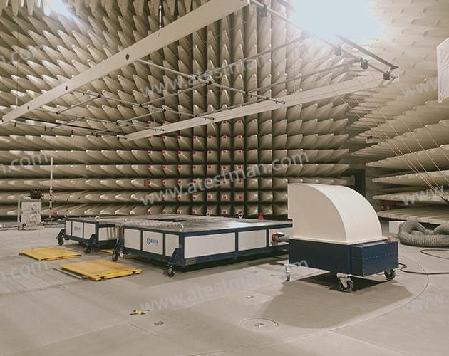
Embedded EMC/EMI Chassis Dynamometer
The embedded dynamometer system generally consists of a drum unit and a dynamometer unit that simulate the load before and after, and the distance between the drum units is adjustable. Embedded dynamometers are generally embedded in the turntable and can rotate with the turntable; or embedded in the raised floor. Before the test, according to the wheelbase of the vehicle, adjust the moving axle unit of the dynamometer to the required distance. The interface will input the vehicle into the hub, lock the vehicle front and rear through the ratchet strap, connect the exhaust pipe, and start test.
The dynamometer system has the following characteristics:
·Each dynamometer unit is an independent unit for modular assembly.
·Each dynamometer unit can carry out independent torque or speed control to simulate road load.
·Can be customized design according to user needs.
·The spacing of the multi-axis dynamometer is adjustable to adapt to vehicle testing with different wheelbases.
·It can be equipped with automatic driving robot, exhaust emission system, vehicle windward system, etc.
·The unique shielding technology can meet the Class5 requirements of CISPR25.
·The dynamometer has high torque and speed control accuracy and high repeatability.
·The dynamometer can be embedded in the turntable or under the raised floor.
·The vehicle fixing device is integrated with the dynamometer body, which is firm and reliable.
·It has a vehicle tire burst detection device.
·With vehicle centering detection device.
Recommended dynamometer parameters:
| Type | Prated (kW) | Frated (N) (b) / 轴 | Vmax (km/h) | Vrtated (rpm) | F2 (N)@ Vmax / 轴 |
| ECD-A22-X(a) | 22 | 2600 | 120 | 60 | 1300 |
| ECD-B34-X | 34 | 3000 | 120 | 60 | 2035 |
| ECD-B74-X | 74 | 6500 | 120 | 60 | 4400 |
(a) X—indicates the number of axles of the dynamometer (for example: four-wheel drive vehicles, generally use 2-axis drive dynamometer);
(b) Frated—represents the traction of a single drive shaft of the dynamometer. The overall traction force of the dynamometer system is the number of active axles of the dynamometer multiplied by the traction force of a single axle;
System performance
1 Working Conditions
1)Power:
·Voltage: 400V AC, 50Hz~60Hz, 3~+PE
·Grounding resistance≯2Ω
·Max current consumption: 145A
·The power supply entering the anechoic chamber control room needs to be filtered by a filter:
·Voltage: 220VAC, 50Hz~60Hz
·Max current consumption: 15A
2)Compressed air:0.4MPa~0.6MPa
2 EMC Performance
1)Emission:
·10dB under the limits of CISPR22
·Frequency range:150kHz~1GHz
·Measurement distance:10m
2)Emission, electrical:
·10dB under the limits of GB/T 18387-2008, SAE J551-5:2004-01
·Frequency range:150kHz~30MHz
·Measurement distance:3m
3)Emission, magnetic:
·10dB under the limits of GB/T 18387-2008, SAE J551-5:2004-01
·Frequency range:150kHz~30MHz
·Measurement distance:3m
4)Immunity:
·Continuous field strength:200V/m
·Frequency range:10kHz~18GHz
3 Dynamometer
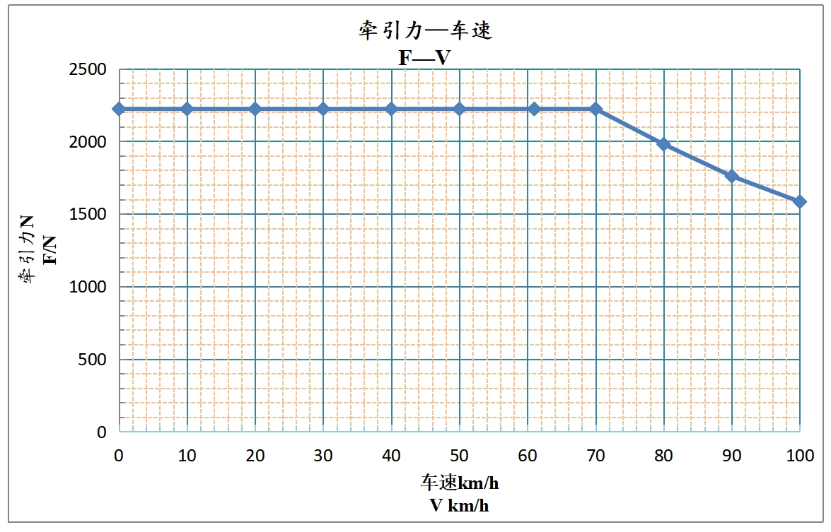
The induction asynchronous servo motor is controlled by four quadrant frequency converter, which can realize the speed and torque control of the dynamometer. Each set of dynamometer and frequency converter are integrated into a unit for complete shielding. The dynamic control of the dynamometer and the feedback of measurement parameters are realized through optical fiber communication between the controller and each frequency converter.
The rated power of a single dynamometer is 22.5kW, and the traction speed characteristic curve of each axle dynamometer(45kW):
4 Rollers
The roller is in direct contact with the vehicle tire, and the surface has a certain roughness, which is used to simulate the road friction. The dynamometer adopts double rollers to facilitate the vehicle in place. The surface of the rollers is sprayed with hard chromium alloy, which can simulate the road friction. The rollers are assembled structure. Both ends of the rollers are supported by heavy grease lubricated spherical roller bearings, which are balanced after assembly.
Technical data:
| Diameter rollers | 240mm |
| Width rollers | 6 00mm |
| Roller Material | carbon steel |
| Roll Coating | Chrome (Metco 2 – 13% Metal Spray) |
| Coating Thickness | 200 um |
| F riction C oefficient | Better than 0.8 |
| Surface R oughness | 300±50um |
| S urface H ardness | Better than 135 Brinell |
| Concentricity | 0.25 mm |
| Maximum Run-Out | 0.25 mm |
| Balance Grade | G2.5 |
| Maximum Axle load | 20 00kg |
5 Vehicle approach bridge
The vehicle approach bridges have stamping anti-skid structure on the surface. The end of the approach bridges are overlapped on the dynamometer frame through the locating pin, and the other end are placed on the surface of the floor. The walking surface of the approach bridges are plated with hard chromium to prevent rust and wear.
6 Wheelbase Adjusting Device
The dynamometer unit are independent modules, which can move and adjust the wheelbase according to the actual size of the vehicle. The two dynamometer units are connected and fixed through a support frame and a moving beam.
7 Roller brake system
When the vehicle enters the chassis dynamometer, the rollers are braked. The brakers are controlled by pneumatic solenoid valves. When the pneumatic solenoid valves are turned on, the brakes will brake the rollers. When the pneumatic solenoid valves are turned off, the brakes will be released automatically.
When the brakers are turned off, please put the vehicle in neutral, release the hand brake, manually rotate the vehicle tire, and observe whether the rollers can rotate to identify the breaker is released. If it cannot rotate, it means that the brakers aren’t released and the braking system needs to be checked.
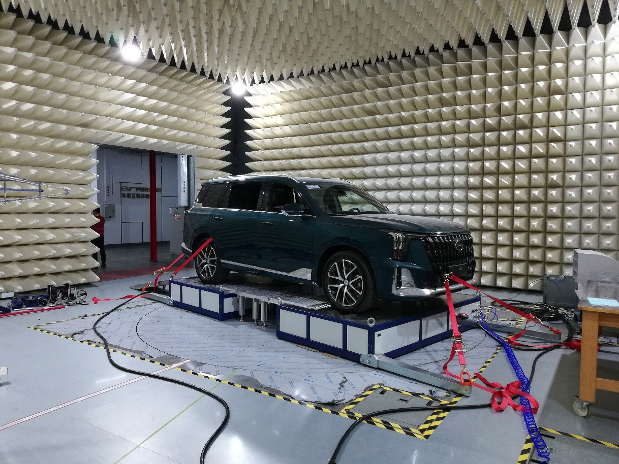
8 Vehicle Fixing Device
The vehicle fixing device includes two high-strength heat-resistant lashing straps. One end is connected with the hook on the steel frame of the chassis dynamometer, and the other end is connected with the hook at the front and back ends of the vehicle. Through the ratchet mechanism, it is convenient to fasten the vehicle.
·Tensile strength: 5000N/set
·Length adjustment: 1.0m to 6.0m
9 Cooling Fan System(optional)
The vehicle cooling fan provides effective cooling for the vehicle and tires, and can remotely control the wind speed of the cooling fan, which can be associated with the vehicle speed. The drainage cover on the upper part of the fan is made of plastic, which can adjust the direction of the wind.
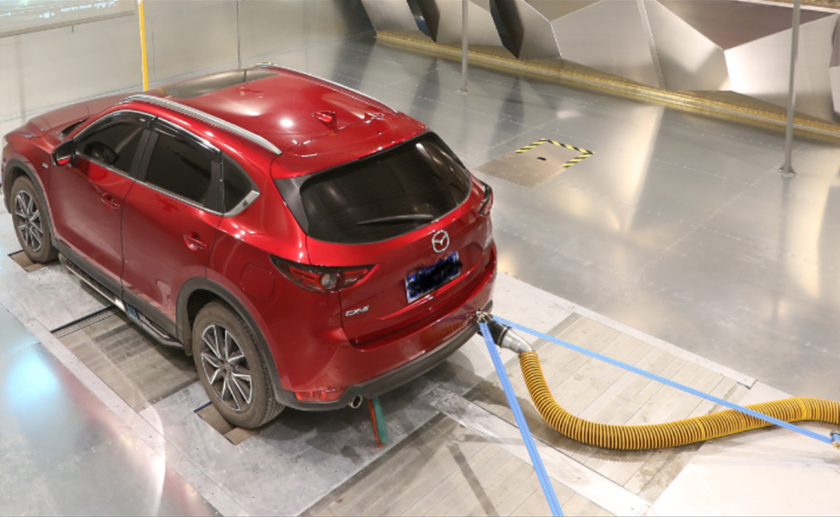
10 High Temperature Exhaust Pipe (optional)
For fuel vehicles or hybrid electric vehicles, exhaust emission devices are provided, which can be quickly connected with the exhaust pipe of the vehicle to discharge the exhaust into the exhaust emission treatment pipeline of the anechoic chamber
11 Actuator unit for Accelerator and Brake
The throttle and brake actuators are pneumatic actuators. The pneumatic actuator can be controlled automatically and manually to realize the control of vehicle brake pedal.
1)Accelerator actuator:
·Moving range: 0~150mm
·Force range: 0~200N
2)Brake actuator:
·Moving range: 0~150mm
·Force range: 0~200N
3)Pneumatic requirement:0.6bar
12 Remote Control System
The operator terminal can be connected to a test computer through another Ethernet interface and be remotely controlled from there.
Monitor and computer form a unit. The Windows 7 operating system is embedded installed on a compact flash card.
The chassis dynamometer, and the fans are controlled via the control software.
The communication of the control computer is done via TCP/IP. The application software can be installed on any other computer.
The following data can be accessed.
·Speed
·Torque
·Acceleration
·Cooling Fan
·The throttle and brake actuators
·Error messages
13 Functions of the Chassis Dynamometer
1)Constant speed:
·Speed and acceleration is determined at the control software interface.
·During the race, you can set a new velocity and acceleration.
2)Master and slave synchronization
·The vehicle drives on the chassis dynamometer. A wheel of the vehicle is defined as master.
·Non driving wheel of the vehicle can rotate as the same speed as the master wheel.
3)Custom operating point
·On the basis of a table (a base is defined with a continuous time and a speed) a function of speed over time can be defined by up to 250 points.
·You can define speed or road resistive torque each wheel.
4)Const. Resistance
·You can define constant resistance regardless of the speed(Conform to the speed torque characteristic of dynamometer).
5)Road simulation
The system can provide a series of dynamometer inertia simulation, and simulate the road load according to the equation:
RL = F0 + F1VX + F2Vn + I dv/dt + mg * (Grad/100)
| RL | Road Load (Force at roller surface) |
| F0, F1, F2 and n | Road load model coefficients |
| F0 | Coefficient of Friction Force independent of velocity |
| F1 | Coefficient of Friction Force dependent of velocity |
| F2 | Coefficient of Windage Force |
| n | Velocity Exponent Variable for F2 term (range 1.1 to 3.0) |
| x | Velocity Exponent Variable for F1 term (range 0.8 to 1.2)(If fitted) |
| V | Linear velocity at roller surface |
| I | Inertia - electrically simulated |
| dv/dt | Acceleration |
| m | Mass |
| g | Gravity |
| grad | Gradient |
14 Security
Mushroom shaped emergency stop button is installed on the console. In case of emergency, the emergency stop button can be pressed, and the dynamometer will cancel the power, the rollers are not braked.
If the system detects that the torque, speed and temperature exceed the set limits, it will also automatically trigger the alarm.
15 Software
The main functional modules of the software include: system control module, data acquisition module, data recording module, data display module, communication module, data playback module, print processing module, sensor calibration module, function setting module, help document module.
Connect with the right expert now.
Atestman offers solutions across your project development, delivery and supply globally,
so we need your help to match you with the right experts in the right place.


")