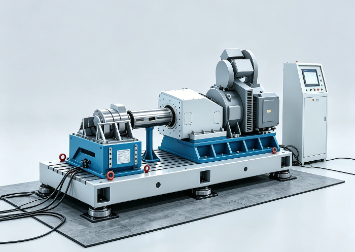
A high-speed dynamometer system measures torque, speed, and power output from electric powertrains across a controlled load range. Selecting the right system is critical for validating motor efficiency, inverter behavior, thermal performance, and drivetrain durability.
atestman
delivers high-speed dynamometer solutions trusted by automotive, military, and aerospace programs worldwide, combining precision measurement hardware with flexible test automation.
Match Dynamometer Architecture to Powertrain Type
High-speed dynamometer
systems fall into three main architectures. The correct architecture depends on the electric powertrain under test and the data the engineering team must collect.
AC Dynamometer
An AC dynamometer uses a regenerative motor drive to absorb or drive torque at high speeds, typically above 10,000 rpm. It offers high accuracy, four-quadrant operation, and clean energy feedback. AC dynamometers are the standard choice for EV motor end-of-line testing and efficiency mapping.
A mid-range AC system covering 18,000 rpm and 1,500 Nm peak torque handles most passenger-vehicle powertrain development programs. Higher-speed units above 25,000 rpm are required for next-generation traction motors used in high-performance EVs.
DC Dynamometer
A DC dynamometer uses a direct-current load motor with a resistive or regenerative bank. It delivers high torque at low speed and suits durability cycles on drivetrain components. DC units cost less up front, but they generate more heat and occupy more floor space.
DC systems remain a practical choice for long-run durability testing where constant torque at moderate speed is the primary load profile.
Eddy Current Dynamometer
An eddy current dynamometer uses an induced-current brake to apply load. It is mechanically simple and requires minimal maintenance. Eddy current units are most often used for steady-state performance checks. They cannot motor the test article, so transient testing capability is limited.
Evaluate Critical Specification Ranges
Specifying a high-speed dynamometer begins with the operating envelope. A system that does not match the device under test will produce misleading data and force costly retrofits.
-
Maximum rotational speed (rpm)
-
Continuous and peak torque capacity (Nm)
-
Power absorption rating (kW)
-
Inertia simulation range (kg-m²)
-
Speed and torque measurement accuracy class
-
Cooling method (air, water, oil)
Engineers should oversize peak torque by at least 20 percent to absorb transient spikes during motor characterization. For example, a motor rated at 500 Nm peak should be tested on a dynamometer with at least 600 Nm peak capacity. This margin prevents torque clipping during acceleration and regenerative braking tests.
Accuracy class selection directly affects measurement confidence. A system accuracy class 0.1 or better ensures data quality for efficiency certification and published performance claims. Class 0.2 may be acceptable for production end-of-line pass-fail screening where relative comparisons matter more than absolute precision.
Confirm Test Cell Integration Capability
A dynamometer must connect cleanly to the larger test cell, including data acquisition, climate control, battery simulation, and vehicle-level automation. The right system integrates with common automation platforms and supports industrial fieldbuses. Compatibility checklists should be reviewed before procurement to avoid integration delays.
Battery simulation is a key integration point for EV testing. A regenerative dynamometer feeds power back to the grid during braking events.
During motor development the test cell requires a programmable DC power supply or battery simulator. This equipment replicates pack voltage, state of charge, and internal resistance under dynamic load.
Atestman
provides integrated cell solutions that pair the dynamometer controller with battery simulation hardware and software for a seamless test sequence.
Communication Protocols
Look for native support of CAN, CAN FD, Ethernet/IP, EtherCAT, and Profinet. Open APIs shorten the path from commissioning to first test. A supplier that provides pre-built LabVIEW or Python drivers reduces software integration risk.
Data Acquisition
A
high-speed dynamometer
should sample torque, speed, current, voltage, and temperature synchronously at rates above 10 kHz. Synchronized channels are required for inverter switching analysis and motor control loop validation.
Multi-channel power analyzers paired with the dynamometer controller create a single data pipeline. This setup eliminates time skew between electrical and mechanical measurements.
Compare Common Configurations
The following table summarizes representative system classes for EV powertrain development. Values reflect typical industrial ranges and should be confirmed against each supplier's published data sheets.
| Configuration |
Max Speed (rpm) |
Peak Torque (Nm) |
Power (kW) |
Best Fit |
|
Compact AC
|
12,000
|
500
|
250
|
E-motor EOL
|
|
Mid-range AC
|
18,000
|
1,500
|
600
|
Powertrain dyno
|
|
High-speed AC
|
25,000
|
800
|
800
|
Traction motor
|
|
DC durability
|
6,000
|
3,000
|
400
|
Drivetrain cycles
|
|
Eddy current
|
8,000
|
1,200
|
300
|
Steady-state QA
|
Plan for Service, Calibration, and Long-Term Support
Procurement decisions should look beyond the test stand. Long-term ownership depends on calibration intervals, spare parts lead time, and on-site service coverage.
-
Documented ISO 17025 calibration options
-
Mean time to repair (MTTR) targets
-
Spare parts kit at commissioning
-
Remote diagnostics and software updates
A supplier with regional engineering support reduces downtime and protects project timelines. atestman operates an international service network with field engineers who support overseas project deployment and acceptance testing.
B2B Technical Reference Table
| Parameter |
Typical Industrial Range |
Notes |
|
Speed accuracy
|
+/-0.05 percent of reading
|
Class 0.1 encoders
|
|
Torque accuracy
|
+/-0.1 percent FS
|
Traceable to national standards
|
|
Sampling rate
|
10 kHz to 100 kHz
|
Inverter switching analysis
|
|
Inertia simulation
|
0.1 to 50 kg-m²
|
Real-time digital twin
|
|
Operating temperature
|
-10 C to 45 C
|
Climate chamber integration
|
|
Footprint
|
6 to 25 m²
|
Depends on power class
|
Conclusion
A correctly specified high-speed dynamometer is the foundation of a credible EV powertrain validation program. The right system combines the correct architecture, a realistic specification envelope, and clean test cell integration, all backed by long-term service support.
Atestman brings more than a decade of testing and simulation expertise to every dynamometer cell, with patented hardware, certified calibration, and field engineers ready to support your project from concept through acceptance.
Request a Rapid Sourcing Quote from atestman to size the right high-speed dynamometer for your EV testing program. Contact atestman Engineering Team for Free Custom Design Support and accelerate your next powertrain milestone.
FAQ
What is the difference between a high-speed dynamometer and a standard chassis dynamometer?
A high-speed dynamometer is a component-level test stand that couples directly to an electric motor or gearbox shaft. A chassis dynamometer measures a complete vehicle on rollers. Component-level dynamometers reach higher speeds, collect motor-level electrical data, and isolate the test article from vehicle variables such as road load and windage.
How fast should an EV motor dynamometer spin?
Most traction motors reach 15,000 to 25,000 rpm at peak speed. The dynamometer must exceed the motor's maximum rated speed by at least 10 percent to provide a safe overspeed margin for inverter calibration and field-weakening tests.
Can one dynamometer test both motor and inverter together?
Yes, an integrated test cell with a dynamometer, power analyzer, and battery simulator can validate motor and inverter as a single system. This approach records inverter switching losses, motor control response, and thermal interactions in a single run, reducing test time and improving data correlation.
What certification should a dynamometer supplier hold?
A qualified supplier should operate under ISO 9001 quality management and offer ISO 17025 calibration for torque and speed measurement. atestman holds more than 10 national and international certifications and supports traceable calibration programs for global EV programs.
How long does commissioning usually take?
A standard high-speed dynamometer cell typically commissions in 8 to 12 weeks, including mechanical foundation work, electrical integration, control system tuning, and acceptance testing with calibration artifacts. atestman supports overseas project deployment through dedicated field engineers and a documented commissioning protocol that shortens ramp-up time.